Solar Panels in Series vs. Parallel: What You Need to Know
A solar panel has two output leads. Before connecting anything, you need to know which one is positive and which one is negative.
Once you begin connecting multiple panels, the next question is whether they should be wired in series, parallel or some combination of both.
That decision changes the voltage and current delivered by the array. It also determines whether the array works properly with your charge controller or inverter—or exceeds what the equipment was designed to handle.
This guide explains how to verify panel polarity, how each wiring configuration works and which specifications must be checked before making the final decision.
Previous lesson: How to Read a Solar Panel Label
Series vs. Parallel: The Quick Answer
| Configuration | Physical connection | Voltage | Current |
|---|---|---|---|
| Series | Positive to negative | Adds together | Remains approximately the same |
| Parallel | Positives together and negatives together | Remains approximately the same | Adds together |
| Series-parallel | Series strings connected in parallel | String voltage remains | String currents add |
The easiest way to remember it is:
Series adds voltage. Parallel adds current.
The total potential wattage of the panels does not magically change because of how they are connected. The configuration changes how that power is delivered.
How to Identify Solar Panel Polarity
Sometimes the positive and negative leads are clearly marked on the panel, cable or junction box. The documentation may also identify them.
Don’t assume connector shape alone guarantees polarity. A previous owner could have replaced or incorrectly installed a connector.
If I’m working with a panel and I’m not absolutely certain, I verify it with a multimeter.
What You Need
- A solar panel exposed to enough light to produce voltage
- A properly rated multimeter
- Standard meter probes or MC4 multimeter test leads
- A marker or label maker if the leads aren’t identified
Basic Safety
The demonstration in the video uses one individual panel. An unknown series string can produce dangerously high DC voltage.
Before testing:
- Verify that the meter and probes are rated for the voltage being tested.
- Confirm the leads are connected to the meter’s voltage ports—not its current-testing port.
- Inspect the probes and cables for damage.
- Avoid touching exposed conductors.
- Don’t connect or disconnect permanent MC4 connections while the circuit is carrying current.
If you aren’t certain what you’re testing, stop and determine the expected voltage first.
Set the Meter to DC Voltage
Set the multimeter to DC volts. Some meters automatically detect AC or DC, while others require DC voltage to be selected manually.
The panel does not need perfect full sunlight for a polarity test. It only needs enough light to produce a readable voltage.
Connect the Meter
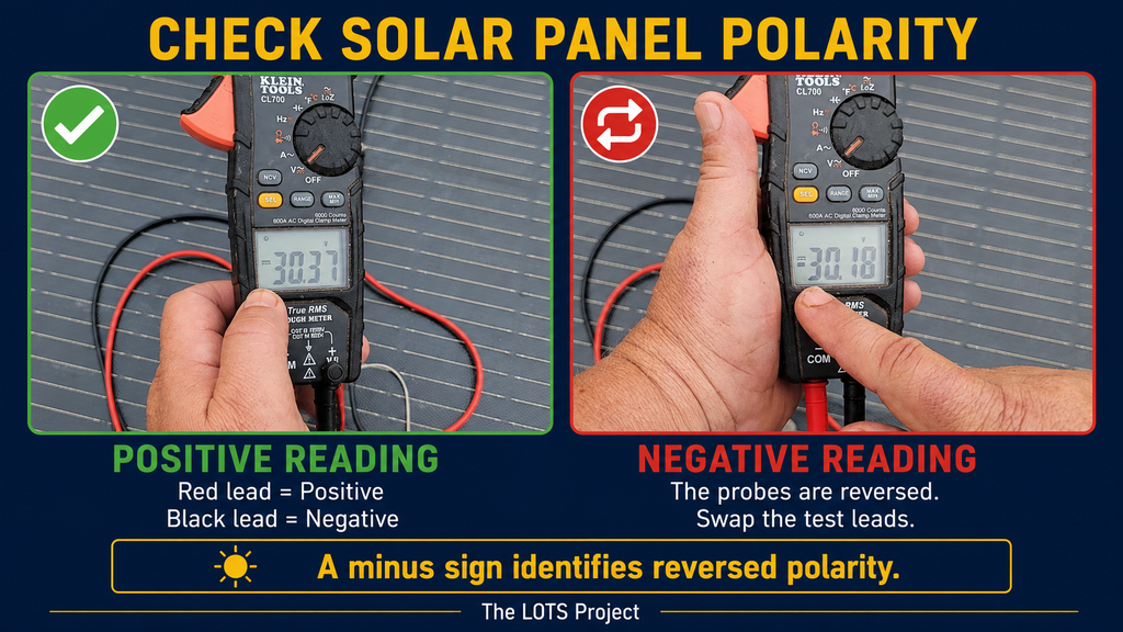
Connect the red meter probe to one panel lead and the black probe to the other.
If the display shows a positive voltage, the red probe is connected to the panel’s positive lead and the black probe is connected to its negative lead.
If the display shows a negative voltage, the probes are reversed.
For example:
30.4Vmeans the assumed polarity is correct.-30.4Vmeans the probes are reversed.
A negative reading does not automatically mean the panel or meter has been damaged. Provided the meter is properly configured and rated for the voltage, the minus sign is simply identifying reversed polarity.
Once the polarity is confirmed, mark the leads if they aren’t already clearly identified.
Using MC4 Multimeter Test Leads
You can test panel voltage using normal pointed multimeter probes, but holding both probes against MC4 contacts can be awkward.
MC4 test leads plug into the multimeter at one end and connect to the panel leads at the other. They provide a secure connection and leave your hands free to read or operate the meter.
I modified my dedicated test leads by removing their locking tabs because they will be repeatedly connected and disconnected while testing a large group of panels.
That modification is only for dedicated test equipment.
Do not remove the locking mechanisms from MC4 connectors used in a permanent solar installation. The locking connection helps prevent the connectors from separating and maintains their intended weather-resistant seal.
The Example Panels
We’ll use simple numbers so the math doesn’t bury the electrical concept.
Assume every panel produces:
- 40 volts
- 8 amps
- Approximately 320 watts
The wattage calculation is:
40V × 8A = 320W
Two panels provide approximately 640 watts of total rated power. Three provide approximately 960 watts.
The way we connect them changes the array voltage and current, but it doesn’t create additional panel capacity.
Wiring Solar Panels in Series
To connect two panels in series, connect the positive lead of one panel to the negative lead of the next.
That leaves one unused negative lead at one end of the string and one unused positive lead at the other. Those become the string’s output leads.
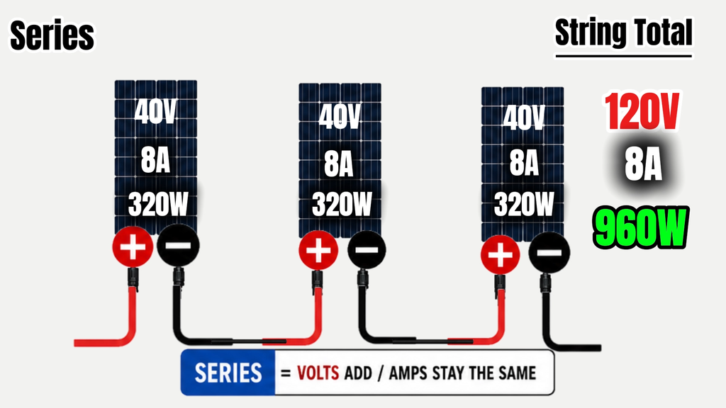
When identical panels are connected in series:
- Voltage adds together.
- Current remains approximately equal to one panel.
Two Panels in Series
Each panel produces 40 volts at 8 amps:
40V + 40V = 80V
The current remains approximately 8 amps:
80V × 8A = 640W
The two-panel string produces approximately:
- 80 volts
- 8 amps
- 640 watts
Three Panels in Series
Add a third identical panel:
40V + 40V + 40V = 120V
The current remains approximately 8 amps:
120V × 8A = 960W
The three-panel string produces approximately:
- 120 volts
- 8 amps
- 960 watts
Advantages of Series Wiring
Series wiring increases voltage without increasing the string current.
That can be useful when sending power a significant distance between the array and the equipment. Higher current generally requires larger conductors and can produce more voltage drop and resistive loss.
My array may be approximately 100 to 150 feet from the equipment, so array voltage, current and conductor size will be major design considerations.
Series wiring may offer:
- Higher array voltage
- Lower current than an equivalent parallel configuration
- Reduced voltage drop for a given wire size and distance
- Simpler connections between panels
- Easier access to an inverter or controller’s MPPT operating range
That does not mean you should simply connect every panel in one enormous series string.
Series Voltage Limits
Every charge controller, inverter or all-in-one unit has a maximum allowable PV input voltage. It will usually also have an MPPT operating range and possibly a separate startup voltage.
When calculating the possible maximum voltage of a series string, use the panel’s Voc, or open-circuit voltage—not only Vmp.
If one panel has a Voc of 50 volts and ten are connected in series:
50V × 10 = 500V Voc
That still isn’t necessarily the highest voltage the array could reach.
Cold solar panels can produce a higher voltage than the Voc printed at Standard Test Conditions. The final design must include the panel’s temperature coefficient and the lowest temperature the array could experience.
Never stack the printed Voc values right against the equipment’s maximum rating without accounting for cold-weather voltage.
We’ll perform that calculation later using the actual panels, local temperatures and EG4 equipment planned for my system.
Series Wiring Trade-Offs
Series wiring also has disadvantages:
- The string voltage can exceed equipment limits.
- Shading or a weak panel can reduce the output of the string.
- Panels with different current characteristics may not work well together.
- Higher DC voltage requires greater care and appropriately rated equipment.
- One disconnected or failed connection can interrupt the entire string.
With mismatched panels in series, the string’s current is generally constrained by the lowest-performing panel. Bypass diodes can help under certain shading conditions, but they do not make mismatched or shaded panels irrelevant.
Wiring Solar Panels in Parallel
To connect panels in parallel:
- Connect positive leads together.
- Connect negative leads together.
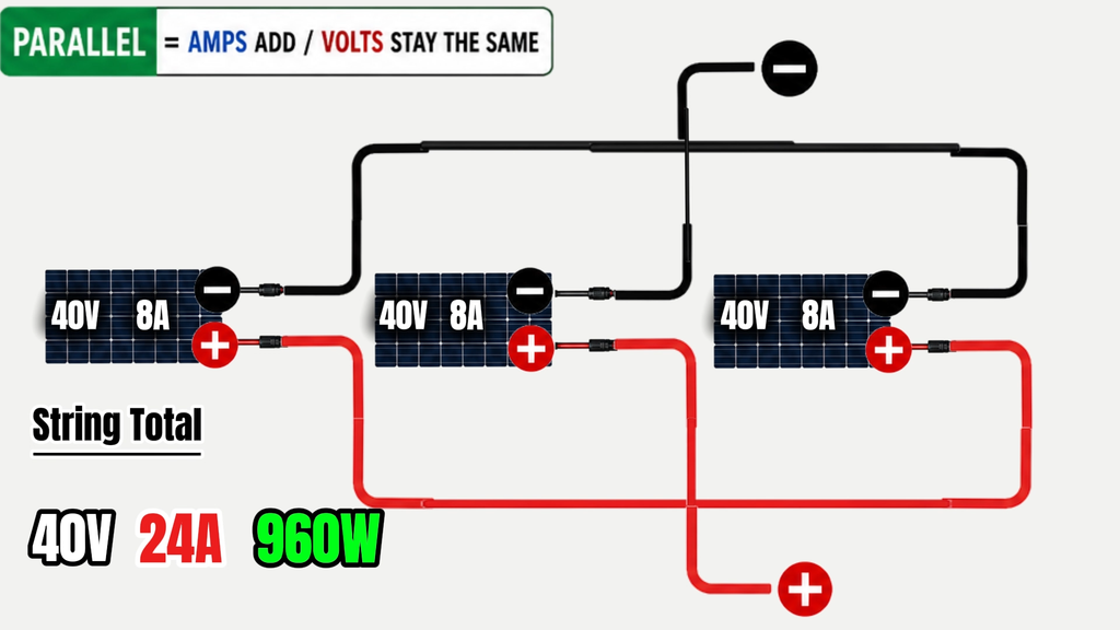
When identical panels are connected in parallel:
- Voltage remains approximately equal to one panel.
- Current adds together.
Two Panels in Parallel
Each panel produces 40 volts at 8 amps.
The voltage remains approximately 40 volts:
8A + 8A = 16A
The two-panel parallel array produces:
- 40 volts
- 16 amps
- 640 watts
The wattage calculation is:
40V × 16A = 640W
Three Panels in Parallel
Add a third identical panel:
8A + 8A + 8A = 24A
The voltage remains approximately 40 volts.
The three-panel parallel array produces:
- 40 volts
- 24 amps
- 960 watts
The calculation is:
40V × 24A = 960W
How Parallel Connections Are Made
Unlike a basic series string, multiple positive and negative leads can’t ordinarily plug directly into one another.
For a small number of panels, MC4 branch connectors—often called Y-connectors—can combine the leads.
With two panels:
- Two positive leads enter a branch connector and leave as one positive output.
- Two negative leads enter another branch connector and leave as one negative output.
The branch connector does not electrically create the parallel configuration by itself. The circuit is parallel because all positives are connected together and all negatives are connected together.
The connector is simply the physical device used to make those connections.
Combined Current After the Connection
Current adds at the parallel connection.
If three panels each produce 8 amps, the output conductor after they are combined may carry approximately 24 amps under operating conditions.
That means everything downstream must be designed for the combined current, including:
- Conductors
- Connectors
- Disconnects
- Charge-controller or inverter inputs
- Overcurrent protection
- Other system components
The panel’s Isc and the required design factors must be considered when calculating conductor and protection requirements. The simple Imp examples used here are meant to demonstrate how the configuration works—not complete a final wiring calculation.
When a Combiner Box Makes Sense
Branch connectors may be practical for a small number of panels or strings. Continually stacking more branch connectors together is not necessarily the right approach for a larger array.
A combiner box provides a central location where multiple strings can be brought together into one larger output.
Depending on its design, a combiner box may include:
- Individual string overcurrent protection
- Disconnects
- Surge-protection devices
- Monitoring
- A consolidated array output
Combiner-box selection and overcurrent protection deserve their own treatment later in the series.
For now, remember that branch connectors and combiner boxes are methods of physically creating the connections. The electrical rule remains the same:
Positives connect with positives, negatives connect with negatives, and current adds.
Advantages of Parallel Wiring
Parallel wiring can be useful when:
- Array voltage must remain lower.
- Multiple series strings need to be combined.
- The system has specific input-current capabilities.
- Different portions of an array need more electrical independence.
- The design uses multiple controllers or MPPT inputs.
Parallel configurations may also behave differently under partial shading, although the actual result depends on the array, panel characteristics and equipment.
Parallel Wiring Trade-Offs
Parallel wiring increases current.
Higher current can require:
- Larger conductors
- More attention to voltage drop
- Additional overcurrent protection
- Branch connectors or a combiner box
- Higher-current-rated equipment
- More complicated wiring
Panels connected in parallel should also have reasonably compatible operating voltages. Significant voltage mismatch can reduce performance because the panels are forced to operate around a shared voltage.
Neither series nor parallel is automatically better. The correct choice depends on the entire system.
Series-Parallel Solar Wiring
Many larger arrays use both series and parallel connections.
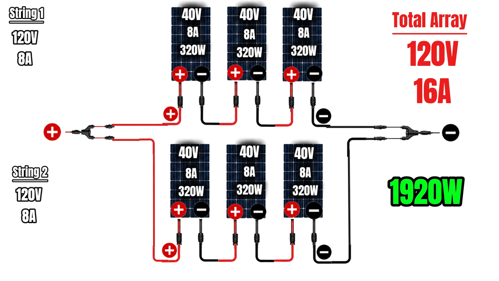
Suppose we have six identical 40-volt, 8-amp panels.
First, connect three panels in series:
- String voltage: 120 volts
- String current: 8 amps
- String power: 960 watts
Then build a second identical three-panel string:
- String voltage: 120 volts
- String current: 8 amps
- String power: 960 watts
Finally, connect those two complete strings in parallel.
Because the strings are connected in parallel:
- Voltage remains approximately 120 volts.
- Current adds to approximately 16 amps.
The completed six-panel array produces approximately:
- 120 volts
- 16 amps
- 1,920 watts
The calculation is:
120V × 16A = 1,920W
The configuration is often described as 3S2P:
- 3S means three panels in series per string.
- 2P means two strings connected in parallel.
How to Choose the Right Configuration
There is no universal answer. Before choosing series, parallel or series-parallel, check:
Panel Specifications
- Pmax
- Vmp
- Imp
- Voc
- Isc
- Temperature coefficients
- Maximum series-fuse rating
- Maximum system voltage
Equipment Specifications
- Maximum PV input voltage
- MPPT operating-voltage range
- Startup voltage
- Maximum input current per MPPT
- Maximum short-circuit current per input
- Number of available MPPT inputs
Installation Conditions
- Number of panels
- Lowest expected temperature
- Distance between the array and equipment
- Available conductor sizes
- Shading
- Panel orientation
- Roof or ground-mount layout
- Whether different groups of panels should use separate MPPT inputs
The array must work inside all of those limitations—not merely produce the desired number of watts.
Common Series and Parallel Mistakes
Using Vmp to Check Maximum String Voltage
Use temperature-corrected Voc when checking the string against the equipment’s maximum PV-input voltage.
Ignoring Combined Current
Current adds in parallel. The conductor and equipment after the combining point must handle the combined output.
Assuming Connector Shape Proves Polarity
Verify polarity when there is any uncertainty, particularly with used or modified panels.
Mixing Random Panels
Panels with different electrical characteristics can sometimes be used together, but careless mixing can reduce output or exceed equipment limits.
Disconnecting MC4 Connectors Under Load
MC4 connectors are not general-purpose switches. Interrupting a live DC circuit can create an arc and damage the connector or injure the person handling it.
Removing Locks From Permanent Connectors
The modification shown in the video is limited to dedicated test leads. Permanent array connectors should retain their locking and weather-sealing features.
Tools and Equipment Used
Disclosure: The following are affiliate links. If you purchase something through one of these links, I may earn a commission at no additional cost to you.
- ALLPOWERS 200W flexible solar panel
- Klein Tools CL710 multimeter — the current version replacing the discontinued CL700 used in the video
- MC4 multimeter test leads
- Signature Solar and EG4 equipment
I used a Klein CL700 in the video because I’ve owned and relied on it for about a decade. That model is no longer available on Amazon, so the link above goes to the newer CL710. You don’t need either specific model for this test, but the meter and test leads must be properly rated for the voltage being measured.
Series vs. Parallel FAQ
Is series or parallel better for solar panels?
Neither is universally better. Series increases voltage, while parallel increases current. The correct configuration depends on panel specifications, equipment limits, temperature, wire distance and installation conditions.
Does series wiring increase wattage?
Adding panels increases the array’s total potential wattage. Series wiring changes how that power is delivered by adding voltage while current remains approximately the same for identical panels.
Does parallel wiring increase wattage?
Adding panels increases total potential wattage. Parallel wiring adds current while voltage remains approximately the same for identical panels.
Can I connect different solar panels in series?
It may be possible, but the string current will generally be constrained by the lowest-current panel. Voltage limits and all other specifications must still be checked.
Can I connect different panels in parallel?
It may be possible when the panels have compatible operating voltages, but mismatched Vmp values can reduce performance. Input-current limits and overcurrent protection must also be considered.
What does 3S2P mean?
It means three panels are connected in each series string, and two identical strings are connected in parallel.
The Rules to Remember
When identical panels are connected:
- Series: Voltage adds; current remains approximately the same.
- Parallel: Voltage remains approximately the same; current adds.
- Series-parallel: Series sets the string voltage; parallel adds the string currents.
Those rules explain the electrical configuration, but they do not complete the system design. Panel specifications, cold-weather voltage, input-current limits, conductor sizing and protection must all be considered before making permanent connections.
My next problem is determining which of my used SunPower panels are actually worth installing. Some have been damaged, moved repeatedly or stored for a long time.
Before designing the final array, I need to test them and separate the usable panels from the ones I don’t want anywhere near the system.
Next lesson: How to Test a Used Solar Panel


2 Comments